WaveForms Application
1.
Getting Started with WaveForms
Install the WaveForms software, if you haven't already. See Installer Details for more information.
Connect your board to your PC using the USB connector and the supplied USB cable.
Start the WaveForms application from the Start Menu > All Programs > Digilent > WaveForms Application > WaveForms.
The application starts and connects to your board.
1.1. Troubleshoot WaveForms
Only one application can be connected to one board at a time. If you get the message “The selected device is being used by another application”, check the taskbar for other applications in use.
If the application is not working as expected, try starting the WaveForms application from the MS Windows Start Menu > All Programs > Digilent > WaveForms Application > WaveForms Safe Mode or the WaveForms application with “clear” parameter.
See the device specific troubleshooting for more information:
1.2. Select an Instrument
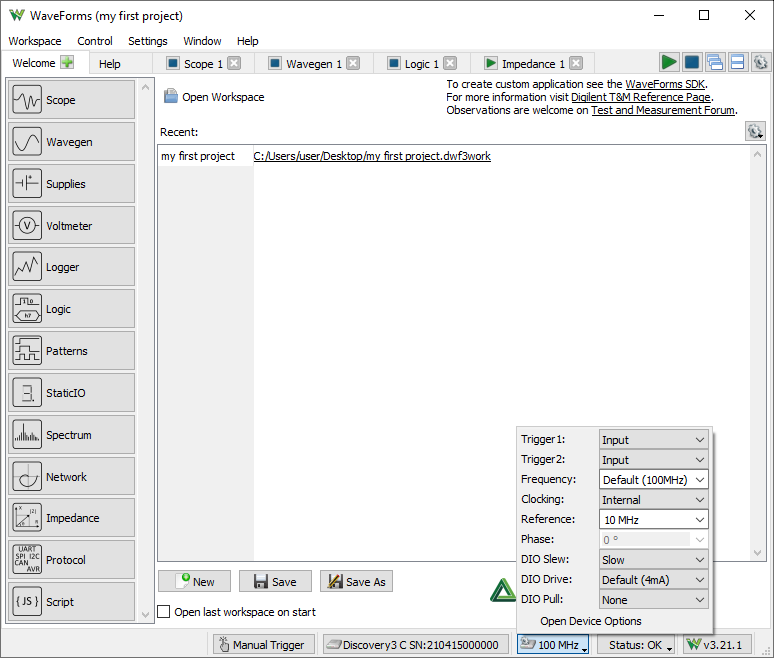
The WaveForms's main window Welcome tab (shown above) has buttons for each instrument: Scope (Oscilloscope), called Meter with DPS3340, Wavegen (Waveform Generator), (Power) Supplies, called DiscoveryPS when used with DPS3340 Select+Dual, Voltmeter, (Data) Logger, Logic (Analyzer), Patterns (Pattern Generator), Static I/O (Digital Input/Output), Spectrum (Analyzer), Network (Analyzer), Impedance (Analyzer), (Curve) Tracer, DMM (Digital Multimeter), Protocol and Script instruments. The instruments can also be opened from the Welcome tab
“+” (add) menu.
An instrument's button is disabled when the selected device or configuration does not support it.
The Settings menu contains the Options, the Device Manager, and Manual Trigger.
The Workspace's Open, Save, and Save as buttons allow the user to load or save WaveForms workspaces.
When an instrument is closed, its state is saved and loaded when reopened. The New button creates a new workspace, which can be used to close the instruments that are currently open while also forgetting the last instrument configurations.
The status bar of the WaveForms main window displays the device name and serial number, as shown below. Clicking on this will open the Device Manager.
The following button opens the Device Options.
The status button opens a drop-down listing system monitor information, depending on device it shows voltages, temperature, power consumption...
The Run/Stop All buttons start or stop all the instruments. In case multiple tools are opened using the same resource, like Scope and Spectrum Analyzer, the last used one will be started. If Script tool is opened only this will be started.
The following two buttons switch between Tabbed and Docking Windows.
The last gear button opens the Application Options.
1.3. The Workspace and Project
The workspace refers to any open instruments and their current state. The workspace can be loaded and saved with the Open and Save/Save As buttons in the WaveForms's Welcome tab.
The workspace and instrument project can be saved in one of the following modes selected by the save filter:
- without acquisition: saves only the Oscilloscope reference channels and data in tabs, Logic Analyzer tabs, custom Wavegen waveforms, and Pattern Generator custom data.
- with acquisition: also saves all buffered data in Oscilloscope and Logic Analyzer, captures in Spectrum, Network and Impedance Analyzer.
The workspace files are associated with WaveForms. When you open a workspace (double-click on a *.dwf3work file) and WaveForms is running, it will be opened with the last used application instance. Otherwise, if WaveForms is not currently running, it will open with a new application instance.
The project refers to an instrument and its current state. The project can be loaded and saved with the Open and Save buttons in each instrument.
The project files are associated with WaveForms. When you open a project (double-click on a *.dwf3scope, *.dwf3wavegen, *dwf3logic, ... file) and WaveForms is running, it will be opened with the last used application instance. Otherwise, if WaveForms is not currently running, it will open with a new application instance.
The New button closes the current project. It can also be used to clear the last settings of the instruments.
The Extract/Compress unpacks the workspace archive. It can be used to extract raw capture data and configuration files.
The Compare can be used to compare multiple workspaces, listing capture device Serial Numbers, date-times, highlighting duplicate SNs.
2. Options
The Options window allows you to select various display and configuration preferences.
To open the Options window, select the Settings / Options menu from the WaveForms window.
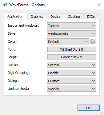
Application options:
- Instrument windows: Specifies how the instrument windows are opened; it can be one of the following options:
- Separate: separate windows.
- Tabs: tabs in main window.
- MDI: multiple document interface.
- Docking: docked to main window.
- Style: Selects the application GUI style. The available options depend on the system. It is recommended to restart the application after a change.
- Analog/Digital color: Selects the color for analog or digital instrument plots.
- Font: Selects the application font.
- Script: Selects the font used in the code editors.
- Locale: Selects the locale to be used for decimal symbol and list separator.
- Digit Grouping: Selects the decimal digit grouping for Data, Event view time columns and few other place.
- Dialog: Selects the file dialog to be operating system's native or custom style.
- Update check: Selects update checking interval or disables it.
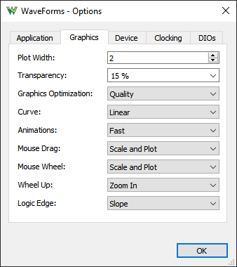
Graphics options:
- Plot width: Adjusts the default line thickness in plots. Custom width can be adjusted for each plot.
- Transparency: Adjusts the plot transparency.
- Graphics optimization: Adjusts the balance between quality and speed.
- Curve: Selects the curve drawn between analog sample points, linear or smooth.
- Animations: Selects the animation speed of value adjustments or disables the animation.
- Mouse Drag: Enables or disable the mouse drag action on drawings scale and/or plot area.
- Mouse Wheel: Enables or disable the mouse wheel action on drawings scale and/or plot area.
- Mouse Up: Selects the mouse wheel direction.
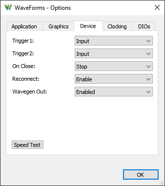
Device options:
See the device description for available options and details.
- Trigger #: Trigger pin can be configured to be input (default) or to be driven by an instrument's trigger signal and also to be driven low or high for digital output purpose.
- On Close: Selects the behavior on software disconnect from device:
- Continue: Keep the instruments running, like Power Supplies, Wavegen and Patterns Generator outputs active after closing the application. Note that workspace/project saving and export dialog will stop the instruments.
- Stop: Stop the instruments, but keep the device operational to prevent temperature drift on next connection.
- Shutdown: Shutdown the device for minimal power consumption.
- Reconnect: Enable or disable the auto-reconnect to the device after connection drop or device reset.
- LED brightness: Adjusts the LED brightness on Digital Discovery in percentage.
- USB Limit: Specify the maximum USB current the device can consume, for Analog Discovery 1 and 2.
- USB Power: Keep the USB supply ON even when connecting AUX supply, for Analog Discovery 2, 3. With this option the device won't stop when disconnecting the auxiliary supply.
- Audio Output: Enable or disable the audio output, for Analog Discovery 1 and 2.
- Wavegen Output: Enable or disable the Wavegen output relay, for ADP3450/ADP3250, ADP2230.
.
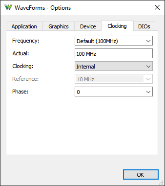
Clocking options:
See the device description for available options and details.
- Frequency: Lets you adjust the system frequency used for ADC, DAC and DIOs.
- Actual: Shows the actual value.
- Clocking: Lets you select between Internal clocking, or Reference Clock Output or Input.
- External: Lets you adjust the Reference Clock Output or specify the Input frequency.
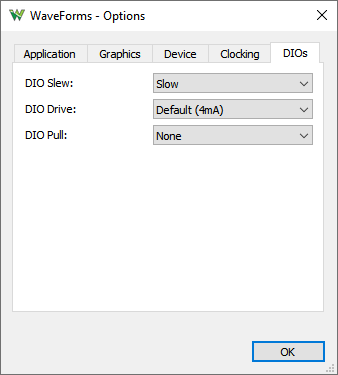
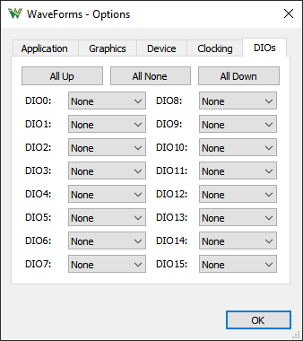
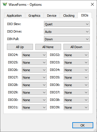
DIO options:
See the device description for available options and details.
- DIO/DIN Slow/Drive: Lets you adjust the DIO (and Trigger IO) drive strength and slew rate.
- Pull Lets you set pull up, down, keeper or none for DIOs (and Trigger IO).
- Digital Threshold Lets you set the digital input threshold. For AD3 lets you select between 1.4 V and 0.6 for low voltage signals. Note the digital output is still 3.3 V
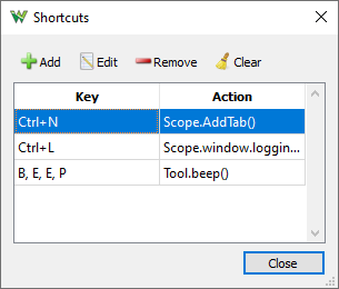
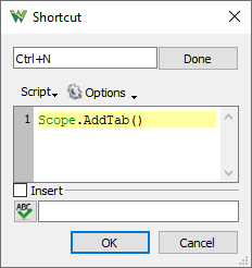
2.1 Shortcuts
Shortcuts can be added which will execute application level scripts. See the Script for details. Make sure the added hotkeys are not in conflict with existing ones used in the application and instruments.
3. Device Manager
The Device Manager allows you to select the device and configuration to use with the WaveForms application.
To open the Device Manager, select the Settings / Device Manager menu or click on the window's status bar device button from the WaveForms window.
The Select + Dual button lets you connect and control to two devices from the same application instance.
- Either to two identical devices to control these at the same time, to double the Scope, Wavegen and DIO channels. The Trigger IOs will be used to synchronize the device.
The reference clock option is available with ADP3X50, Analog Discovery 3, ADP2230. The clock phase may need to be adjusted for stable triggering which is affected by the trigger wiring and DIO drive/slew setting. The Dual Delay option can be used to compensate the latency, in Scope under Time/Options, in Wavegen, Logic Analyzer and Pattern Generator under the top-right Gear options.
When devices without reference clocking capability are used the signals may show jitter and shift over time.
The dual mode has some limitations since one trigger line is used for cross-triggering so Scope and Logic Analyzer can't be used at the same time but Digital channels can be added to Scope interface. The Wavegen and Pattern Generator uses the same trigger line which is used to start the respective instrument. The dual mode for this is working with no trigger option and zero wait.
Mixing of Analog Discovery 1, 2 and 3 is supported, but the Oscilloscope and Logic Analyzer capture size of AD3 will be limited to the AD1,2 device buffer size.
- The additional device can also be a power supply device (DPS3340). In this case the the DPS can be controlled by DiscoveryPS tool in the main tab's instrument list.
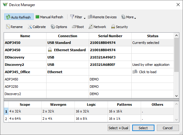
Devices list: Select the device you want to use. The Demo devices allows you to explore WaveForms' capabilities without a physical device being connected to the PC.
Configurations list: Select the configuration you want to use for the selected device. The configurations have different device buffer-memory distributions for the instruments and other capabilities, such as digital input standards.
- Auto Refresh: Click to perform repeated refresh of device list.
- Manual Refresh: Click to perform one refresh of device list.
- Filter: The dropdown menu lets you select which device types to list: USB, Network, Remote, Demo and Sound Card.
- Remote Devices: Opens a dialog to manage remote network devices, see ADP3450/ADP3250.
- More
- Connect to: Lets you connect to a device. See SDK manual for details.
- Local Passwords: Lets you manage the Local Passwords
- Secure Connection: Check to enable network communication TLS encryption.
- NetTimeout: Lets you specify the network discovery timeout for Manual Refresh.
- List ADP5000: For troubleshooting purposes, it will list the ADP5000 devices using the low level library
- Prog AD1,2,3,ADS,DD: Same as the following.
- The My device is not listed will let you reprogram the USB IDs of Analog and Digital Discovery device. This could be erased by other USB development applications.
- Rename: Lets you change the device user name.
- Calibrate: The Calibrate button opens the Calibration window.
- Options: drop-down menu or table context menu shows some of the Device Options and the Force Programming button which forces the device reconfiguration.
- Default Configuration lets you choose the default configuration for the selected device type (by device ID) or for this (by Serial Number), and reset configuration options.
- Boot: Lets you select the device Boot mode for ADP3450/ADP3250.
- Network: Lets you configure the Network Settings for ADP3450/ADP3250.
- Users: Lets you manage the Device Users for ADP3450/ADP3250.
4. Device Calibration
Each device is calibrated during manufacturing test procedure. The calibration data is stored in the device non-volatile memory.
The Device Calibration window allows you to calibrate (fine-tune) a device's analog components, such as the read-voltage levels of the Oscilloscope or Voltmeters, the output level of the Waveform Generator, Adjustable Power Supplies of the Electronics Explorer board, or the Oscilloscope and Waveform Generator of the Analog Discovery device.
The calibration frequency depends on the requirements. It can be done monthly, yearly, biannually or never, or before any critical project.
Start the Device Calibration window from the WaveForms main window Settings / Device Manager.
The following window will open. The items in the calibration list depend on the selected device type.
It is recommended to let the device to heat up for 5-10 minutes, to reach its operational temperature.
Clicking on the links in the Calibration tab to perform calibration of subsystems.
The Wizard can be a long process. It is better to perform the calibrations steps separately.
The Oscilloscope offset error can be compensated in the Scope instrument under Time and Channel options, Zero offset.
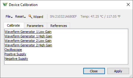
- File:
- Open: loads a previously saved calibration parameter file.
- Save: stores the current calibration parameters to a file.
- Reset:
- Discard changes: cancels any changes made after opening the Device Calibration window or pressing the Apply button.
- Load Factory: loads the default calibration parameters.
- Reset to Zero: resets the calibration parameters to zero.
- Apply: saves the calibration changes made to the device.
- Calibration tab: allows you to double-click a listed item to start its calibration.
- Parameters tab: allows you to review the calibration parameters.
- References tab: allows you to review the measured calibration and reference values.
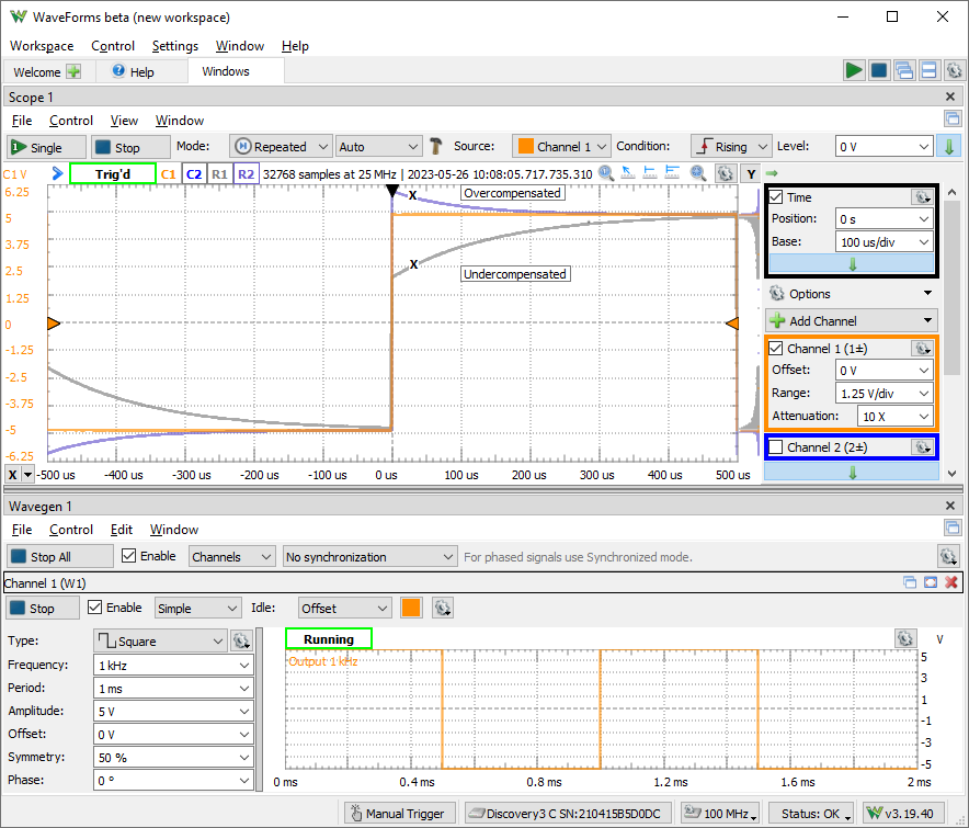
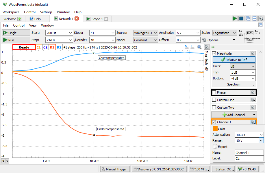
4.1 Probe Compensation
The 10X oscilloscope probes need to be compensated with the used channel. The input impedance of devices and channel may differ which needs to be tuned to match the 10X probe.
To perform this, generate a 1-5kHz square signal and adjust the trimmer on the BNC end, until you see a correct square wave in the oscilloscope. The Network Analyzer can also be used for the adjustment.
5. Common Interfaces
5.1. Menu
The menu strips of the instrument windows generally have:
- File menu where project open and save operations can be performed.
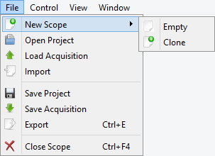
- New
- Empty: opens a new empty instrument.
- Clone: opens a new instrument with the the same configuration as the current instrument.
- Open Project: opens an instrument project.
- Load Acquisition: loads earlier save acquisition data, available in Scope and Logic Analyzer.
- Import: import data from file, available in Scope and Logic Analyzer
- Save Project: saves an instrument project to file.
- Save Acquisition: save acquisition data, available in Scope and Logic Analyzer.
- Export: exports data or screenshot from one of the opened views. See Export for more information.
- Close: closes the instrument.
- Control menu with single, run, and stop controls.
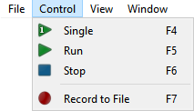
- Single: starts a single acquisition.
- Run: starts repeated acquisitions or continuous generation.
- Stop: stops the instrument.
- View menu where child windows, toolbars, and other visual options can be selected.
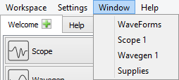
- Window
menu contains links to the main window and all open instrument windows of this application.
- Help
menu contains:
- Browse: opens Help in the default browser.
- Home Page: opens the Digilent web page.
- About: opens the About dialog to show the software version and support contact.
5.2. Lists
The mouse operations for lists, like for measurements, Logic Analyzer, Pattern Generator signals, are as follows:
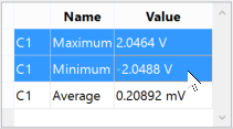
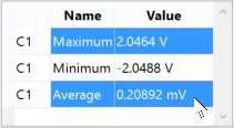
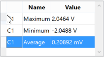
 left mouse click: selects an element.
 shift and left mouse click: selects an element range.
 control and left mouse click: adds an element to the selection list.
 mouse move with pressed left button on row header: moves the selected elements.
- Delete button: removes selected elements.
5.3. Plots
The center of the plot is marked with grid lines. Each vertical and horizontal line constitutes a major division. For linear scales, these are laid out in a 10x10 division pattern. The tick marks on the axis between major divisions are called minor divisions. For logarithmic scales, major ticks are shown for each decay value and minor ticks for 2,3,4... points.
The plots and axes allow the following scaling adjustments:
- With mouse wheel (or two finger scroll on touchpad) over left or bottom axis, the channel range or time base is adjusted. For start/stop (frequency) and top/bottom (dB) values, the right/upper side of the axis adjust the start/bottom value and the left/lower side the stop/top value.
- With mouse wheel on the plot zooms in or out around the cursor position.
- With left-button mouse drag, on left or bottom axis, the offset or position is adjusted. For top/bottom values both levels are shifted.
- With right-button mouse drag performs zooms in or out having in the the middle the press position.
- Having the Ctrl key pressed speeds up and Shift slows down the respective operation. The Alt key swaps the left-right or range-offset adjustment.
- The double-click on the axis sets the offset, position, start or top value to zero.
- After focusing by clicking on axis or plot, the keyboard arrow keys can also be used to change the offset and range, to move and scale the plot.
Each plot has a button in the top-right corner which opens a drop-down menu (or mouse right-click) containing options for:
- Add Label: adds a new editable text label to the plot.
- Clear Labels: removes all the labels from the respective plot.
- Color: selects the color theme for this plot.
- Plot Width: sets the thickness of the waveform, expressed as points.
- Global Options: lets you adjust the graphics options of the application.

The Quick Measure allows you to take measurements by moving the mouse cursor. It has the appearance of a vertical cursor and it displays values such as amplitudes, periods, or frequencies where it intersects with the waveforms present in the view. This can be enabled and disabled with the toggle button in the top-right corner, or by double-clicking on the plot. Clicking on the plot locks or unlocks the Quick Measure to its current position.

The Show entire capture sets the time position/base or start/stop frequencies to show the entire capture.

The Cursors are used to measure waveform data. They can be used to indicate certain properties of the waveform, such as bandwidth or channel limits. Using delta cursors, you can make measurements for power change with frequency or time. These can be added by pressing the X button in the plot bottom left corner. The Y cursors in the Scope main time plot can be added by pressing the Y button in the top right corner. The first cursor is by default added as a normal cursor, the following ones are added as delta of the first cursor, displaying the difference. The cursors position can be modified by a mouse drag, keyboard arrow keys, or adjustment control in the cursor's drop-down menu. Mouse button middle click removes the cursor. The cursors can be selected with the channel number shortcut, pressing 1, 2,..
The Cursor view enabled in the instrument's View menu shows the position and measurements in a table. The cursor's drop-down menu and table contain adjustment controls for the reference cursor selection, position, delta value relative to reference cursor, and remove button. For horizontal cursors, the position is expressed in horizontal axis units while the vertical value is shown in intersection with each waveform.
5.4. Docking Windows
The docking window's functionality gives you flexible organization of docking windows within the parent window.
The windows can be dragged by their top border. When dragging is above the margins of the parent window, it will indicate the drop region. If you release the mouse, the child window will be docked to the corresponding margin. If you position a child window above another child window with same parent, it can dock in tabular mode. Releasing a window outside of drop regions makes the window float.
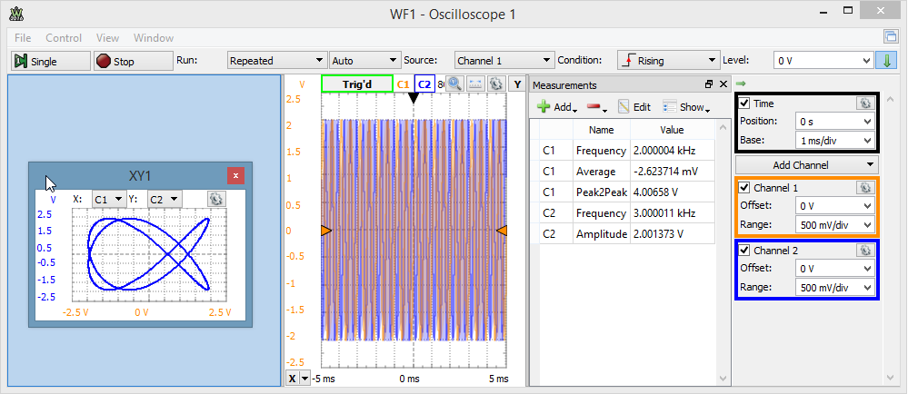
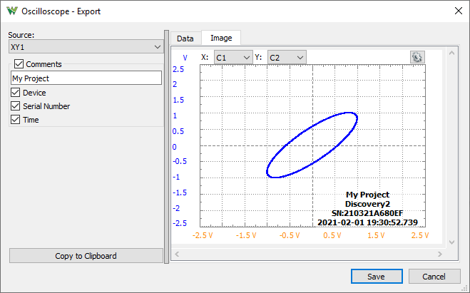
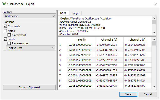
5.5. Export
The Export dialog lets you save the data or screen-shot. The data can be saved as CSV (comma separated values), TXT (tab delimited values) and NI TDMS format. By checking the save options, the following information will also be saved:
- Comments: title, device name, serial number, and software version.
- Notes: lets you add custom notes to the saved file
- Header: column header names, for instance: Time (s), C1 (V), etc.
- as comment: appends # to each Notes and/or Header line
- Label: first column can be time or frequency, depending on the selected source.
- Reverse order: the labels and data rows are saved in reverse order
- Time: select label format between: Relative Time from trigger position, absolute local DateTime or UTC time with different resolution: seconds, milli, micro, nano-seconds.
The screenshot image can be saved in various image formats with options to overlay Comments like Device Name, Serial Number, and Time.
5.6. Script
The script editor uses JavaScript language to create custom Math channels in Scope, custom waveform patterns in WaveGen, and Logger channel functions. These expect mathematical functions which will be called and applied to each sample of the input value (data or X).
The specific objects and variables available in each of these can be found under the Insert menu Locals group. Besides these, the standard script elements are the following:
- Mathematical operations: addition “+”, subtraction “-”, multiplication “*”, division “/”, reminder “%”.
- Brackets: parenthesis (), square brackets []
- Constants: Math.E, Math.PI, Math.LN2, Math.LN10
- Functions: Math.log (logarithm), Math.pow (power), Math.min (minimum), Math.max (maximum), Math.sqrt (square root), Math.sine, Math.cos, Math.tan, Math.acos, Math.atan, Math.atan2, Math.abs (absolute value), Math.round, Math.floor, Math.ceil
The custom measurements in Scope expect a more complex script, where the value in the last line is the result. You may need to implement a loop to process the acquisition data.
For further information see Script Code.
5.7. Logging
The Logging tool allows you to save data on each acquisition or to execute custom script code. This is available in the Scope, Logic and Spectrum Analyzer instruments.
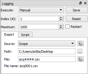
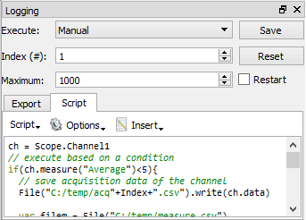
- Execute: selects when the logging will be executed.
- Manual: only by pressing the Save button.
- Each acquisition.
- Each triggered acquisition.
- Index: is the variable that is automatically incremented after each save operation and can be used in file naming in Simple mode.
- Maximum: specifies the limit for Index value for which Simple save operation is performed.
- Repeat: select to restart the Index from value one when the maximum is reached.
- Export
- Source: selects the source of saving which can be acquisition or an opened view. The following options are available:
- Comments: title, device name, serial number, date and time.
- Header: column header names, for instance: Time (s), C1 (V), etc.
- Label: first column can be time or frequency, depending on the selected source.
- Path: specifies the folder where the files will be saved.
- File: specifies the file name. See the options in the right of the File field for available regular expressions to generate file names.
Number sign (#) will be replaced by Index, and more “#” signs indicate zero padding the number.
The expression between square brackets will be replaced by date and time:
| Expression |
Output |
| d |
the day as a number without a leading zero (1 to 31). |
| dd |
the day as a number with a leading zero (01 to 31). |
| ddd |
the abbreviated localized day name (e.g., 'Mon' to 'Sun'). Uses the system locale to localize the name. |
| dddd |
the long localized day name (e.g., 'Monday' to 'Sunday'). Uses the system locale to localize the name. |
| M |
the month as a number without a leading zero (1-12). |
| MM |
the month as a number with a leading zero (01-12). |
| MMM |
the abbreviated localized month name (e.g., 'Jan' to 'Dec'). Uses the system locale to localize the name. |
| MMMM |
the long localized month name (e.g., 'January' to 'December'). Uses the system locale to localize the name. |
| yy |
the year as a two digit number (00-99). |
| yyyy |
the year as a four digit number. |
| h |
the hour without a leading zero (0 to 23 or 1 to 12 if AM/PM display). |
| hh |
the hour with a leading zero (00 to 23 or 01 to 12 if AM/PM display). |
| H |
the hour without a leading zero (0 to 23, even with AM/PM display). |
| HH |
the hour with a leading zero (00 to 23, even with AM/PM display). |
| m |
the minute without a leading zero (0 to 59). |
| mm |
the minute with a leading zero (00 to 59). |
| s |
the second without a leading zero (0 to 59). |
| ss |
the second with a leading zero (00 to 59). |
| z |
the milliseconds without leading zeroes (0 to 999). |
| zzz |
the milliseconds with leading zeroes (000 to 999). |
| AP or A |
use AM/PM display. A/AP will be replaced by either “AM” or
“PM”. |
| ap or a |
use am/pm display. a/ap will be replaced by either “am” or
“pm”. |
| t |
the timezone (for example “CEST”). |
- Script allows you to perform custom save operations with the instrument object (Scope or Logic). See Script.
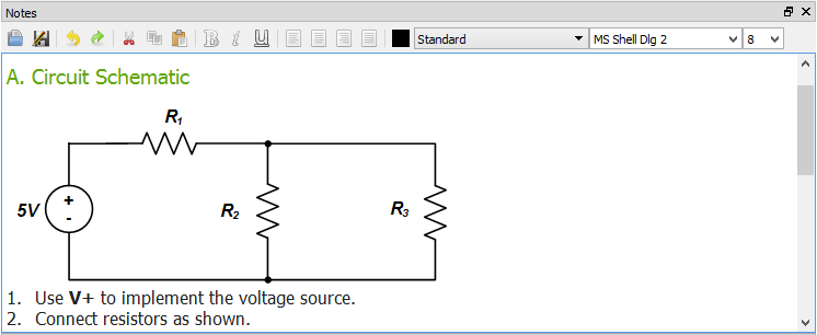
5.8. Notes
The Notes view lets you add description to the projects.
6. States
The active instruments (Oscilloscope, Wavegen, Logic, and Patterns) step through states while acquiring or generating a signal.
The application lets you open multiple instruments (Scope, Wavegen, Logic, Patterns, Logger, Voltmeter, Spectrum, Network, Impedance Analyzer, Tracer...) relying on the same device resource (Scope, Wavegen channels, Logic, Patterns, Supplies, StaticIO). Only one of these instances can control at a time a device resource, the last used instance (Run or Stop press), the other display Busy state.
Like having multiple identical interfaces open only the last started one will capture, the other will be busy.
The Voltmeter, Logger and Spectrum also uses the Scope device resource.
The Wavegen channels are separate device resources, can run independently, except when used in Synchronized mode.
The Network and Impedance Analyzer use Scope and Wavegen 1 channel, by default, also Supplies and StaticIO when used with IA adapter.
The Tracer uses Scope, Wavegen 1 and 2, also Power Supplies and StaticIO when used with Transistor tester adapter.
The Protocol tool uses Patterns device resource to send and Logic to receive data.
6.1. Acquisition States
- Ready: instrument is not running.
- Config: instrument is under configuration or acquisition buffer is prefilled.
- Armed: instrument is armed and is waiting for a trigger event to occur while writing to the buffer.
- Trig'd: acquisition is triggered writing to buffer the needed post-trigger samples. It is useful when repeated acquisitions are running to see whether the trigger condition was met or the acquisition was automatic.
- Auto: acquisition is automatically started and not by the trigger condition.
- Done: single acquisition is completed.
- Stop: instrument was stopped.
- Scan: instrument is running in scan screen or shift mode.
- Error: is displayed if you have just disconnected the device from the PC.
6.2. Generator States
The following diagram illustrates the states of the Arbitrary
Waveform Generator and Digital Pattern Generator.
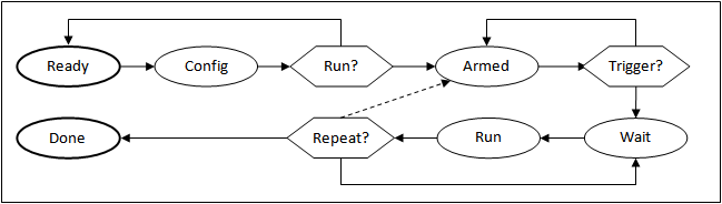
- The instrument leaves the Ready state if it is started with the Run or Run All buttons or any changes have been made.
- The instrument is in the Config state for a short while when the new configuration is applied. It then goes to the Armed state if it is started or changes have been made while running. Otherwise, it goes back to the Ready state.
- In the Armed state, it waits for the trigger. The trigger can come from any other instrument or external source. If 'None' trigger source has been specified, signal generation starts immediately.
- It pauses in the Wait state until the specified wait time elapses.
- In the Run state, signal generation is enabled until the specified run-time elapses. If the continuous option has been specified, it stays in this state until stopped.
- The (Trigger)–Wait–Run cycle is repeated the number of times specified by the Repeat parameter, then it goes to the Done state. If the infinite option has been specified, it always goes back to the Wait state until it is stopped.
The Repeat cycle can be configured to include or exclude Trigger.
- Wait–Run mode: once triggered, will repeat the wait-run cycle for the specified times.
- Trigger–Wait–Run mode: waits for the trigger event each time before entering the Wait and Run states.
If any setting (frequency, duty, signal type, etc.) is modified from any state, it goes right to the Config state. If the instrument was running, it will be started again.
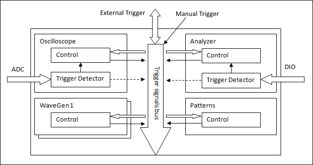
7. Triggers
The Electronics Explorer board has four trigger IO pins, the Analog Discovery has two. They are used by the Oscilloscope, Arbitrary Waveform Generators, Logic Analyzer, and Digital Pattern Generator instruments. The trigger event is by default the rising edge of the trigger signal, but it can be configured to be the falling or either edge.
An instrument's trigger output is high while in Run state.
By default the run time is continuous in Wavegen and Patterns, so these will toggle their trigger outputs when started or stopped.
To have repetitive trigger event specify a finite run time in Patterns and Wavegen, after selecting an other option than "No synchronization".
Any of these instruments can be triggered by any of the trigger signals coming from external pins or the other instruments.
The Waveform Generator channels can function as independent instruments, having their own controller, or in synchronized mode when the selected channels are controlled by one state controller.
The input instruments (Oscilloscope and Logic) have a trigger detector based on their input channels.
The Manual Trigger event is generated by pressing the button under the main window device menu. On the Electronics Explorer board, this trigger event is generated when the board switch is turned to the on position as well.
The None trigger mode configuration in the instruments means that acquisition or generation doesn't wait for a trigger, it starts immediately.
The Auto trigger mode for input instruments means that if the trigger condition doesn't appear in maximum from two seconds and holdoff value plus the specified time span, acquisition is started automatically.
In multiple acquisition mode, when the instruments switch to Auto trigger, subsequent acquisitions are made without waiting for timeout as long as a trigger event does not occur and the configuration is not changed. When a new trigger event occurs or the configuration is changed, the current acquisition is finished and the next one waits for the trigger. It is also the best mode to use if you are looking at many signals and do not want to set the trigger each time.
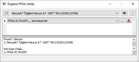
8. FPGA Utility
The FPGA Utility window lets you program DFPGA, CPLD and PROM of Digilent development boards.
9. Installer
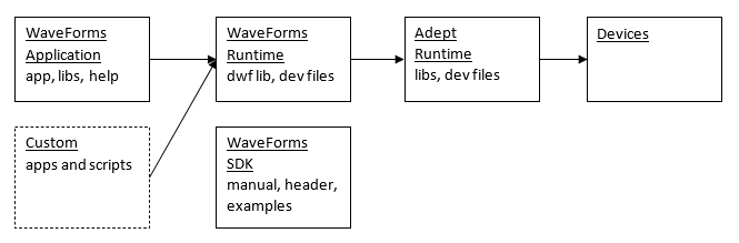
For Microsoft Windows® the digilent.waveforms_v#.#.#_64bit.exe installer contains the following sections:
- Requisites: Microsoft Visual C Runtime packages.
- Adept Runtime: is required for communication with devices, contains USB drivers, libraries and other devices support files
- Analog Discovery Pro 5000 series
- ADP5000 Driver: contains USB driver and dadp5capi.dll for ADP5000 devices
- LabVIEW support: installs newer version of nilciuserapi.dll which enables control for ADP5000 devices using VirtualBench VIs
- WaveForms Runtime: required for custom applications and script. It installs dwf.dlls compiled for x86, x86_64 (amd64) and arm64 architectures, and device support files (configurations, firmware images).
- WaveForms Application: contains application, the required Qt libraries, help, dwf.dll (compiled with Qt for sound card support) and device support files (configurations, firmware images). The application architecture is 64bit ARM/Intel but it is also supported by Windows ARM64.
- WaveForms SDK: contains manual, examples, libs (x86, x86_64, arm64, arm64ec) and header file, see the default location at C:/Program Files (x86)/Digilent/WaveFormsSDK
- The WF SDK/ samples/ dwfcmd command line application can be used for control the device generate and capture signals.
- The digilent.waveforms_v#.#.#_32bit.exe legacy installer packs 32bit WaveForms application and only 32bit Microsoft Visual C Runtime packages.
For MacOS® (>=10.13) the digilent.waveforms_v#.#.#.dmg Apple Disk Image file contains the following:
- WaveForms.app: contains the WaveForms application, Help and the dwf.framework. To install the WaveForms.app, copy it (drag and drop) from the image to the Applications folder. The application architecture is 64bit Intel but it is supported on ARM devices with Rosetta.
- The SDK (manual, examples) are in WaveForms.app/Contents/Resources/SDK
- dwf.framework: can be used by custom application and scripts, either from /Library/Frameworks or bundled in applications. This contains the dwf library and Adept Runtime compatible with x86_64 and arm64 architecture, and device support files (configurations, firmware images). To install the WF Runtime copy the dwf.framework to Frameworks folder.
- The MacOS policy may require the following:
- System Preferences/ Security & Privacy/ General/ Allow apps downloaded from: App store and identified developers
- System Preferences/ Security & Privacy/ General/ Allow anyway/ WaveForms and dwf.framework
- Open WaveForms with Secondary click
For Linux the digilent.waveforms_v#.#.#_[i386|amd64|armhf|arm64].deb|[i686|x86_64|armhf|aarch64]|rpm:
- Installs the waveforms (application static linked to dwf), dwf library (for custom applications and script), and other files: help, device support files, SDK under /usr/share/digilent/waveforms/ samples and manual.
On DEB based distributions install with: sudo apt install ./digilent.adept.runtime...deb ./digilent.waveforms...deb
On RPM based distributions install with: sudo yum install ./digilent.adept.runtime...deb ./digilent.waveforms...deb
The required Qt packages (qt5-qtmultimedia qt5-qtserialport qt5-qtnetwork qt5-qtscript) for WaveForms application are differently named and organized (like Qt5ScriptTools is included in Qt5Script) on some RPM repositories, so these need to be installed manually and digilent.waveforms installation forced.
On openSUSE sudo zypper install libQt5Multimedia5 libQt5Script5 libQt5SerialPort5
- 32-bit ARM digilent.waveforms.adp3X50_x.x.x_armhf.deb special version of WaveForms installer for ADP3X50 which does not contain WF application but only Runtime, dwfcmd and SDK. This also requires digilent.adept.runtime...armhf.deb.
- The dwfcmd command line application can be used for control the device generate and capture signals. The examples can be found in /usr/share/digilent/waveforms/dwfcmd/
- The Adept Runtime digilent.adept.runtime_v#.#.#_[i386|amd64|armhf|arm64].[deb|rpm] needs to be installed separately. This may need to be reinstalled after an OS update, as the udev rules required for devices with FTDI USB (Analog Discovery 1,2,3 and Digital Discovery) may be deleted.
| Windows |
| ...64bit.exe | 64-bit AMD/Intel, also works with ARM64 |
| ...32bit.exe | legacy 32-bit Intel OS |
| MacOS |
| ...dmg | 64-bit AMD/Intel, also works with ARM/M1,2,3 |
| Linux |
| ...amd64.deb or ...x86_64.rpm | 64-bit AMD/Intel |
| ...i386.deb or ...i686.rpm | 32-bit Intel |
| ...arm64.deb or ...aarch64.rpm | 64-bit ARM |
| ...armhf.deb or ...armhf.rpm | 32-bit ARM |
| ...adp3X50_..._armhf.deb | 32-bit ARM |
The installer for Windows® has the following command line arguments:
- /S (silent mode) installs or updates WaveForms without the installation wizard. If you use this option while WaveForms is running, installation might fail.
- Launch the installer from admin command prompt, otherwise the installer will ask for admin rights.
- To overcome the driver installation ("Windows Security/device software") confirmation, add the certificate to the system before launching the installer with the following command:
CertUtil -addstore TrustedPublisher nic.cer
The "nic.cer" certificate file can be exported from certmr.msc application from Trusted Publishers "National Instruments Corporation" after it was once installed with "Always trust software from..." checked.
- /CurrentUser or /AllUsers creates and installs shortcuts for the current user or for all users. This option works for fresh installs of WaveForms. Updates or additions use the option from the first installation. To change this option, WaveForms must be uninstalled and then installed again.
- /QuickLaunch creates Quick Launch shortcuts (only Windows XP®).
- /Update only already installed components are selected.
The following are the command line arguments for the WaveForms application:
- -safe-mode launches the application in safe mode without loading the saved options and recent workspace list.
- -runscript runs the Script tool with the current script tab.
- -stopscript stops the Script execution with the current script tab.
- -abortscript aborts the Script execution with the current script tab.
- -script myscript.txt/js opens and runs the script file.
- -script "file 2" selects the tab with name and runs the script.
- -app # specifies which application to load the workspace or run the script. With zero value it refers to the last used or focused application and with negative value it will open a new application.
- -closeapp closes the application, this may prompt save dialog.
- -killapp closes the application without saving workspace.
- *.dwf3work loads the workspace archive. When used together with runscript argument it does not ask for saving workspace changes.
- *.ini loads extracted workspace.
For projects, the instrument is opened and project loaded:
- *.dwf3scope Scope - Oscilloscope.
- *.dwf3wavegen Wavegen - Waveform Generator.
- *.dwf3logic Logic Analyzer.
- *.dwf3patterns Pattern Generator.
- *.dwf3supplies Power Supplies.
- *.dwf3logger Data Logger.
- *.dwf3static Static I/O.
- *.dwf3spectrum Spectrum Analyzer.
- *.dwf3network Network Analyzer.
- *.dwf3impedance Impedance Analyzer.
- *.dwf3protocol Protocol tool.
- *.dwf3script Script.
For instance:
> C:\Program Files (x86)\Digilent\WaveForms3\WaveForms.exe myworks.dwf3work -runscript
$ waveforms myworks.dwf3work -runscript
When working with multiple devices and WaveForms instances the initial workspace loading will try to connect to the workspace device if it is available by
$ waveforms -app 1 work1.dwf3work
$ waveforms -app 2 work2.dwf3work
$ waveforms -app 1 -runscript
$ waveforms -app 2 -runscript