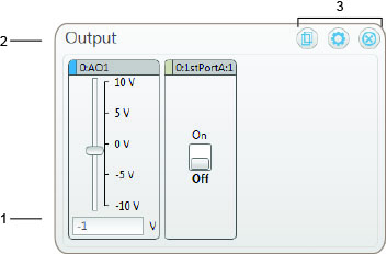
When you add an output channel to an Output display, DAQami creates an output control for users to change the output value when an acquisition is running. The type of control that is created depends on the type of output channel. An example is shown here:

Refer to the callout numbers below for a description of each component on the Output display.
| Callout | Name | Description | ||||||
| 1 | Output controls | An output control is created for each output channel added to the display. The type of control depends on the type of output signal. The control color corresponds to the channel color. Right-click on the control icon to show a context menu with options to remove the channel or change its color. A signal type setting is also available for analog output channels that support hardware pacing. Refer to the Output Channel Controls discussion below. | ||||||
| 2 | Display title | The title of the display (refer to Display Title in Configuring Display Settings). | ||||||
| 3 | Icons | Icons used to copy, customize, and remove the display.
|
Right-click on the display to show a menu with the following options:
Typical controls for each type of output signal are shown here.
The name on the control is specific to the signal name on the selected hardware, and may differ from the controls shown here.
| Output Channel | Control | Description |
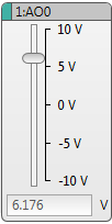
| Analog Output |  Slider control | Use the analog voltage slider control to change the analog output signal during an acquisition. The slider control is the default control created when you add an analog output channel to an Output display Right-click on the control to show a menu with the following options:
|
| Note: Changing an analog output signal with a Slider control affects the frequency of the hardware-paced waveforms on all other AO channels. There is currently no known work-around for this issue. | ||
 Waveform control | Use the analog waveform control to modify waveform settings before or during an acquisition. If the selected device supports analog output scanning, select Signal Type»Waveform from the context menu to change from a slider to a waveform control. To change back to a slider control, select Signal Type»Slider from the context menu. | |
| Digital Output |  Digital switch control | Use the digital switch control to change the high/low state of a digital pin during an acquisition. Right-click on the control to show a menu with the following options:
|
 | Digital square wave control If the selected device supports digital output scanning and all digital bits on the port are configured for output, select Signal Type»Square Wave from the context menu to change from a switch to a square wave control. To change back to a switch control, select Signal Type»Switch from the context menu. | |
| Counter/Timer Output |  | Use the pulse output control to configure the pulse settings before or during an acquisition. |