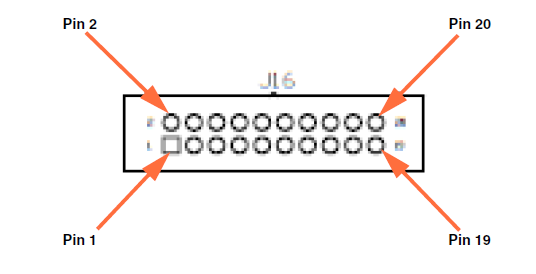
The 20-pin Analog I/O header (J16) brings out all the analog input and output signals on the DT7816. To make wiring signals easier, you can attach the STP781x screw terminal panel to this header.
The following figure shows the Analog I/O header (J16) on the DT7816 module.
The following table lists the pin assignments of the Analog I/O header.
Pin Assignments of the Analog I/O Header (J16)
Connector Pin Number |
Signal Description |
Connector Pin Number |
Signal Description |
1 |
Analog Output 0 |
2 |
Analog Output 0 Return |
3 |
Analog Output 1 |
4 |
Analog Output 1 Return |
5 |
Analog Input 0 |
6 |
Analog Ground |
7 |
Analog Input 1 |
8 |
Analog Ground |
9 |
Analog Input 2 |
10 |
Analog Ground |
11 |
Analog Input 3 |
12 |
Analog Ground |
13 |
Analog Input 4 |
14 |
Analog Ground |
15 |
Analog Input 5 |
16 |
Analog Ground |
17 |
Analog Input 6 |
18 |
Analog Ground |
19 |
Analog Input 7 |
20 |
Analog Ground |