To make wiring easier, you can connect the STP781x screw terminal panel to the DT7816 module. The connectors on the screw terminal panel mate directly to the Analog I/O header, Digital I/O header, and Digital Function headers on the module.
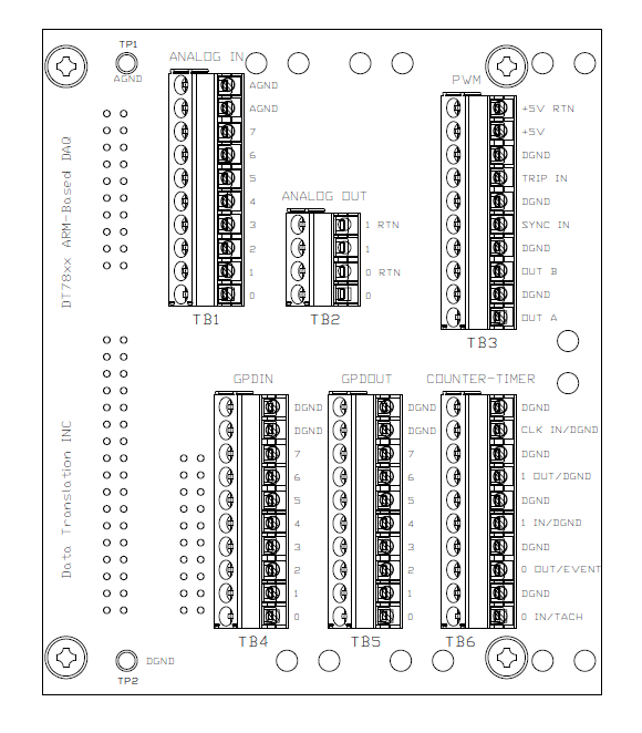
The following figure shows the layout of the STP781x.
The following table lists the screw terminal assignments for the STP781x.
Screw Terminal Assignments for the STP781x
Screw Terminal |
Screw Terminal Name |
Signal Descriptions for the DT7816 |
TB1 - ANALOG INPUT |
AGND |
Analog Ground |
AGND |
Analog Ground |
|
7 |
Analog Input 7 |
|
6 |
Analog Input 6 |
|
5 |
Analog Input 5 |
|
4 |
Analog Input 4 |
|
3 |
Analog Input 3 |
|
2 |
Analog Input 2 |
|
1 |
Analog Input 1 |
|
0 |
Analog Input 0 |
|
TB2 - ANALOG OUTPUT |
1 RTN |
Analog Output 1 Return |
1 |
Analog Output 1 |
|
0 RTN |
Analog Output 0 Return |
|
0 |
Analog Output 0 |
|
TB3 - PWMa |
+5 V RTN |
+5 V Output Return |
+5 V |
+5 V Output (50 mA, maximum) |
|
DGND |
Digital Ground |
|
TRIP IN |
Digital Ground |
|
DGND |
Digital Ground |
|
SYNC IN |
Digital Ground |
|
DGND |
Digital Ground |
|
OUT B |
Digital Ground |
|
DGND |
Digital Ground |
|
OUT A |
Digital Ground |
|
TB4 - GP DIN |
DGND |
Digital Ground |
DGND |
Digital Ground |
|
7 |
General-Purpose Input 7b |
|
6 |
General-Purpose Input 6b |
|
5 |
General-Purpose Input 5b |
|
4 |
General-Purpose Input 4b |
|
3 |
General-Purpose Input 3b |
|
2 |
General-Purpose Input 2b |
|
1 |
General-Purpose Input 1b |
|
0 |
General-Purpose Input 0b |
|
TB5 - GP DOUT |
DGND |
Digital Ground |
DGND |
Digital Ground |
|
7 |
General-Purpose Output 7b |
|
6 |
General-Purpose Output 6b |
|
5 |
General-Purpose Output 5b |
|
4 |
General-Purpose Output 4b |
|
3 |
General-Purpose Output 3b |
|
2 |
General-Purpose Output 2b |
|
1 |
General-Purpose Output 1b |
|
0 |
General-Purpose Output 0b |
|
TB6 - COUNTER-TIMERc |
DGND |
Digital Ground |
CLK IN / DGND |
Digital Ground |
|
DGND |
Digital Ground |
|
1 OUT / DGND |
Digital Ground |
|
DGND |
Digital Ground |
|
1 IN / DGND |
Digital Ground |
|
DGND |
Digital Ground |
|
0 OUT / EVENT |
Reserved |
|
DGND |
Digital Ground |
|
0 IN / TACH |
Tachometer Input |
aThe
DT7816 does not support PWM signals; therefore, screw terminal block TB3
is not used on the STP781x screw terminal panel when used with
the DT7816 module.
bBy
default, general-purpose inputs 0 to 7 are configured as digital input
signals and
general-purpose outputs 0 to 7 are configured as digital output
signals.
cFor
the DT7816, the only signals accessible through screw terminal block TB6
are the tachometer input
and the digital ground signals.