Configuring Sample Rates and Triggers
For each device in the acquisition, you can configure the clock source and sample rates for each type of activated channel on the Sample Rates tab. You can also configure start and stop triggers for an analog input device on the Triggers tab.
Click on the Sample Rates tab and complete the following steps to configure the sample rates for a device:
- Select a device from the Device Panel.
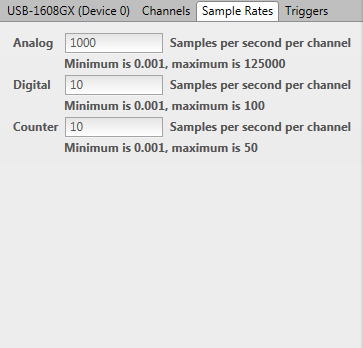
- For most devices, enter the sample rate in samples per second (S/s) per channel for each type of activated input channel – analog inputs in the Analog textbox, digital inputs in the Digital textbox, and counter inputs in the Counter textbox.
For devices that support synchronous analog, digital, and counter operations – also called composite operations – select one of the following clock options:
- Select the Shared Input Clock (Composite) checkbox to pace using one hardware clock to pace all activated input channels from all input subsystems – analog, digital, and/or counter input.
Enter a sample rate in samples per second (S/s) per channel for all activated input channels.
- Clear the Shared Input Clock (Composite) checkbox to select one subsystem to pace using a hardware clock, while all other subsystems are paced using a software clock:
- Analog: Analog input operations are paced with a hardware clock, and all other operations are paced with a software clock.
- Digital: Digital input operations are paced with a hardware clock, and all other operations are paced with a software clock.
- Counter: Counter input operations are paced with a hardware clock, and all other operations are paced with a software clock.
- None: All input operations are paced with a software clock.
- Enter the sample rate in samples per second (S/s) per channel for each activated subsystem – analog inputs in the Analog textbox, digital inputs in the Digital textbox, and counter inputs in the Counter textbox.
Note:
When continuously logging more than 1 million samples per channel, you may experience performance issues depending on the PC that is running DAQami, the number of channels being sampled, the sample rate, and other factors. For optimal performance in this scenario, reduce the sample rate, reduce the number of active channels, and/or install a faster hard drive.
Click on the Triggers tab and complete the following steps to configure triggers for a device:
- Select a device from the Device Panel.
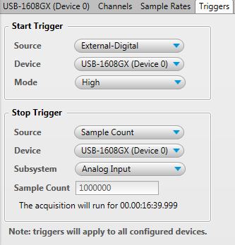
- Select the start trigger source.
- Select the default Manual to start acquiring samples when you click
 or
or  .
.
- Select External-Analog or External-Digital to start acquiring samples when the trigger condition is met.
- Select a device that supports the selected trigger type from the Device list.
- Select a supported trigger mode from the Mode list.
- Select the stop trigger source.
- Select the default Manual to stop acquiring samples when you click
 .
.
- Select Sample Count to stop acquiring samples when specified number of samples are acquired.
- Select a device and device subsystem – analog, digital, or counter input channels – to monitor for sample count.
- Enter the number of samples (Sample Count). The acquisition stops when the specified number of samples are acquired by the selected device subsystem.
Sample rates and trigger settings are stored in a configuration file (.amicfg file when you save the configuration.
Trigger settings apply to all devices in the acquisition.
Note: When using multiple devices, start triggers from one device to another occur as close in time as possible; however, there may be some system-dependent latency between devices.
| Sample Rates Tab Settings |
| Shared Input Clock (Composite) | This checkbox only appears if the selected device supports synchronous analog, digital, and counter operations (composite operations).
- Select this checkbox to use one hardware clock to pace all activated input channels from all input subsystems – analog, digital, and/or counter input.
- Clear this checkbox to select one subsystem option to pace with a hardware clock, while all other subsystems are paced with a software clock.
- Analog: Select this option to pace analog input operations with a hardware clock, and pace all other operations are paced with a software clock.
- Digital: Select this option to pace digital input operations with a hardware clock, and pace all other operations are paced with a software clock.
- Counter: Select this option to pace counter input operations with a hardware clock, and pace all other operations are paced with a software clock.
- None: Select this option to pace all input operations with a software clock.
- Enter the sample rate in samples per second (S/s) per channel for each activated subsystem.
|
| Samples per second per channel textboxes | Depending on the type of device and the type of data being acquired, any combination of the following textboxes may be available to enter sample rates in S/s per channel:
- Analog – If one or more analog input channels are activated, enter the per-channel analog sample rate for each analog channel.
- Digital – If one or more digital input channels are activated, enter the per-channel digital sample rate for each digital channel.
- Counter – If one or more counter input channels are activated, enter the per-channel counter sample rate.
- Composite – If the Shared Input Clock (Composite) is selected, enter the per-channel sample rate for all activated input channels (all input subsystems).
The minimum and maximum sample rates per channel allowed by the device and number of active channels is shown below each text box. |
| Triggers Tab Settings |
| Start Trigger |
| Source | The trigger condition that starts the acquisition. The trigger settings that display update according to the selected device. Click the Source arrow and select a trigger source:
- Manual: The acquisition starts when you click or .
- External-Analog: All devices start acquiring data when an external analog input signal meets the trigger criteria specified by the selected trigger mode on the selected device.
- Rising Edge – The acquisition is triggered when the signal transitions from below the level to above. Once conversions are enabled, the external trigger is ignored.
A Level text box is shown when this mode is selected.
- Falling Edge – The acquisition is triggered when the signal transitions from above the level to below. Once conversions are enabled, the external trigger is ignored.
A Level text box is shown when this mode is selected.
- Rising Slope – The acquisition is triggered when the signal transitions from below low threshold to above high threshold. Once conversions are enabled, the external trigger is ignored.
Low Threshold and High Threshold text boxes are shown when this mode is selected.
- Falling Slope – The acquisition is triggered when the signal transitions from above high threshold to below low threshold. Once conversions are enabled, the external trigger is ignored.
Low Threshold and High Threshold text boxes are shown when this mode is selected.
- External-Digital: Scanning starts when an external digital input signal meets the trigger criteria specified by one of the following Trigger Modes:
- High – The acquisition is triggered when the signal goes above the high level.
- Low – The acquisition is triggered when the signal goes below the low level.
- Rising Edge – The acquisition is triggered when the signal transitions from low to high (TTL trigger).
- Falling Edge – The acquisition is triggered when the signal transitions from high to low.
|
| Stop Trigger |
| Trigger Source |
The trigger condition that stops the acquisition. Click the Source arrow and select a trigger source:
- Manual: The acquisition stops when you click or when the number of samples specified in the Sample Count field are acquired from the analog, digital, and/or counter channels.
- Sample Count: When the selected device and subsystem (analog, digital, or counter channels) acquires the number of samples entered in this textbox, the acquisition stops for all channels on all devices.
|
See Also
Configuring a Device
Configuring Channels
Saving a Configuration File