Use the Channels tab on the Configuration Panel to activate and configure the analog, digital, and counter I/O channels to include in the acquisition. The settings that display are specific to the device selected on the Device Panel.
Channel settings are stored in a .amicfg file when you save the configuration.
Note: When running concurrent input and/or output operations with DAQami – whether among multiple devices or on a single device – there may be time lags between the data being acquired and/or generated for each operation. Although every effort is made to coordinate data timing between subsystems and devices, because all except one susbsystem is started through software, the virtual nature of the trigger for starting each operation results in some variation, particularly in the starting time.
When running composite I/O operations with DAQami using USB-1808 Series or USB-CTR Series devices, all susbsystem operations are synchronized by sharing a single hardware clock.
Note: When continuously acquiring more than 1 million samples per channel, you may experience performance issues depending on the PC that is running DAQami, the number of channels being sampled, the sample rate, and other factors. For optimal performance in this scenario, reduce the sample rate, reduce the number of active channels, and/or install a faster hard drive.
Tip: When selecting channels on this tab, press <Shift> to select multiple contiguous channels at the same time, or <Ctrl> to select and configure multiple non-contiguous channels. To select all channels, click anywhere in the grid and press <Ctrl-A>. The settings selected for one channel are applied to all selected active channels.
Click on the links below to go to the configuration procedure for each channel type:
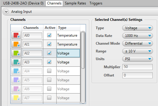
Complete the following steps to configure analog input settings:
| Analog Input Settings | |
| Color swatch | The color applied to the channel icon and channel data on a display. Click to open a color palette and select a color. |
| Channels | The name of each channel on the device. The name is included on each display to which you add the channel. You can enter a new name of up to 25 characters. |
| Active | The checkbox used to activate/deactivate a channel. Select the checkbox for each channel to include in the acquisition. Activated channels are listed on the Device Panel, and active input channel data is logged. Active channels can be added to displays. |
| Type | The analog measurement type(s) supported by the device. |
| Range | The range(s) supported by the device. This column is enabled when Type is set to Voltage. |
| TC Type | The TC types supported by the device. This column is enabled when Type is set to Temperature; it is only visible if the device supports temperature measurements. |
| Channel Mode | If the selected device supports configuring some channels as single-ended and some as differential, select the mode for the selected channel. The default mode is Differential. |
| Data Rate | USB-2408 Series and USB-2416 Series only. When acquiring data with a USB-2408 Series or USB-2416 Series device, the data rate controls the amount of noise filtering on each channel. By reducing the data rate, the averaging of samples increases, and noise drops correspondingly. If low noise is your main concern, select very low data rates starting at 2.5 Hz. At low rates, much of the noise is averaged out of the data, and issues such as reference noise become less important. Refer to the Setting the data rate to control noise filtering discussion below for more information. |
| Units | The unit used to convert the data. Selectable values are specific to the measurement type. Select Custom to create a unit not available on the list. The unit is shown in parentheses after the channel name below the Active Channels list on the Device Panel. |
| Multiplier | The value used to scale data and to calculate the y-axis upper and lower range. This column is enabled when Units is set to Custom. |
| Offset | The value used to offset each data point. This column is enabled when Units is set to Custom. |
Complete the following steps to configure analog output settings:
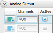
| Analog Output Settings | |
| Color swatch | The color applied to the channel icon and channel data on a display. Click to open a color palette and select a color. |
| Channels | The name of each channel on the device. The name is included on each display to which you add the channel. You can enter a new name of up to 25 characters. |
| Active | The checkbox used to activate/deactivate a channel. Select the checkbox for each channel to include in the acquisition. Activated channels are listed on the Device Panel, and active channels can be added displays. |
Output control: Adding analog output channels to the Output display lets you manipulate the output voltage during the acquisition. If the selected device supports output scanning, you can also modify waveform settings. Refer to the Output Channel Controls discussion for more information about the real-time controls available with analog output channels.
Typical digital settings are shown here. The settings which display are specific to the selected device, and may differ from this example.
Complete the following steps to configure digital I/O settings:
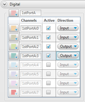
| Digital I/O Settings | |
| Color swatch | The color applied to the channel icon and channel data on a display. Click to open a color palette and select a color. |
| Channels | The name of each channel on the device. The name is included on each display to which you add the channel. You can enter a new name of up to 25 characters. |
| Active | The checkbox used to activate/deactivate a channel. Select the checkbox for each channel to include in the acquisition. Activated channels are listed on the Device Panel, and active input channel data is logged. Active channels can be added to displays. |
| Direction | When the bit direction is configurable, select Input or Output. |
Output control: Adding digital output channels to the Output display lets you manipulate the direction during the acquisition. If the selected device supports output scanning, you can also modify the square wave frequency and duty cycle. Refer to the Output Channel Controls discussion for more information about the real-time controls available with digital output channels.
Typical counter input settings are shown here. The settings which display are specific to the selected device, and may differ from this example.
Complete the following steps to configure counter input settings:
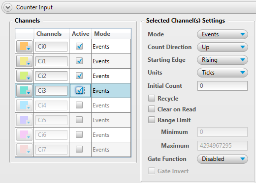
Events mode settings are shown in the image above. To configure a channel for event counting – counting rising or falling edges – complete the following steps:
| Count Direction | Recycle Checkbox | Counter Behavior |
|---|---|---|
| Up | Selected | When the count reaches the Maximum value, the counter rolls over to the Minimum value. |
| Up | Clear | When the count reaches the Maximum value, the counter stops. |
| Down | Selected | When the count reaches the Minimum value, the counter rolls over to the Maximum value. |
| Down | Clear | When the count reaches the Minimum value, the counter stops. |
To configure a channel for frequency counting – counting cycles over a period of time – complete the following steps:

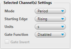
To configure a channel for period counting – calculating the period of a cycle – or Pulse Width counting – measuring the time from the rising edge to the falling edge, or vice versa, on a counter input signal – complete the following steps:
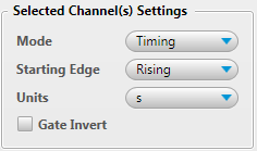
To configure a channel for timing mode – calculating the time between an event on a counter input and a subsequent event on a counter gate – complete the following steps:
| Counter Input Settings | |
| Color swatch | The color applied to the channel icon and channel data on a display. Click to open a color palette and select a color. |
| Channels | The name of each channel on the device. The name is included on each display to which you add the channel. You can enter a new name of up to 25 characters. |
| Active | The checkbox used to activate/deactivate a channel. Select the checkbox for each channel to include in the acquisition. Activated channels are listed on the Device Panel, and active input channel data is logged. Active channels can be added to displays. |
| Mode | The counter mode. The following counter modes are supported (depending on the counter functionality of the device):
|
| Count Direction | When the selected Mode is Events, select Up to count up from Initial count, or Down to count down from Initial count |
| Starting Edge | The edge to count; select Rising to count rising edges, or Falling to count falling edges. |
| Units | The unit used to convert the data. Selectable values are specific to the selected Mode. A custom unit can also be entered for each mode. |
| Initial Count | The starting value when counting up or down. |
| Recycle | Enables the counter to restart counting when a specified value is reached. |
| Clear on Read | Clears the counter after each read. |
| Range Limit | Minimum and maximum values to read. |
| Gate Function: | Enables a specific input to gate the counter. Selectable values are specific to the selected Mode. |
| Gate Invert: | Enables the counter to increment upon an active low/falling edge/gate low signal. |
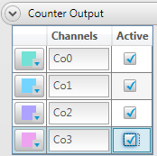
Typical counter output settings are shown here.
Complete the following steps to configure counter output settings:
| Counter/Timer Output settings | |
| Color swatch | The color applied to the channel icon and channel data on a display. Click to open a color palette and select a color. |
| Channels | The name of each channel on the device. The name is included on each display to which you add the channel. You can enter a new name of up to 25 characters. |
| Active | The checkbox used to activate/deactivate a channel. Select the checkbox for each channel to include in the acquisition. Activated channels are listed on the Device Panel, and active channels can be added to displays. |
Output control: Adding counter output channels to the Output display lets you set frequency and duty cycle of the output. Refer to the Output Channel Controls discussion for more information about the real-time controls available with digital output channels.
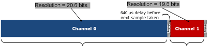
The data rate controls the amount of the noise filtering on each channel in a DAQami acquisition. By reducing the data rate, the averaging of samples increases, and noise drops correspondingly.
If low noise is your main concern, select a very low data rates starting from 2.5 Hz. At low rates, much of the noise is averaged out of the data, and issues such as reference noise become less important.
At higher data rates, higher-frequency noise sources are not averaged out and can begin to be problematic. These noise sources include the noise inherent in the A/D converter itself, which is not reducible. Since TCs can pick up noise in your environment, select a data rate based on the primary noise frequency.
For example, to reduce the effect of 60 Hz noise, select a data rate of 60 Hz (or a supported multiple of 60, such as 10 Hz or 5 Hz).
When acquiring from multiple channels, the sample rate is the same for all channels, but channels with a lower data rate have more filtering, or averaging, performed on the data.
For example, if you set a 10 Hz data rate for channel 0, and a 50 Hz data rate for channel 1, both channels pass the same number of samples per second to the host computer. However, more averaging is performed on channel 0 samples; therefore, channel 0 is sampled at a higher resolution.
The A/D converter on USB-2408 Series and USB-2416 Series devices perform averaging, and the number of averages equals 30,000/data rate. In this example, channel 0 is sampled 3000 times over 100 ms, and all samples are averaged into one sample. Then, channel 1 is sampled 600 times over 20 ms, and samples are likewise averaged into one sample. The final samples are available to you at a maximum rate of about 8 Hz (8.245 Hz).