Use can use rate generation (clock divider) mode to generate a continuous pulse output signal from the counter’s output signal. You can use this pulse output signal as an external clock to pace other operations, such as an analog input or other counter/timer operations.
The pulse output operation is enabled whenever the counter’s gate signal is at the specified level. When the operation is enabled, the counter outputs a pulse of the specified type and frequency continuously. As soon as the operation is disabled, rate generation stops.
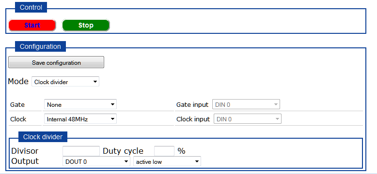
When you choose Clock divider mode from the Counter/Timer page of the web server, the following options are available:
To perform a rate generation operation, perform the following steps:
For Mode, select Clock divider.
For Gate, select one of the following:
None - The operation is enabled immediately when you start the operation. (No general-purpose input signal is required for the gate input when a software gate is used.
External hi - The operation is enabled when the counter’s gate signal is high and is disabled when the counter’s gate signal is low.
If you select this gate type, specify which general-purpose input pin of the Digital I/O header to use for the gate input signal to the counter using the Gate input drop-down box, and ensure that you wire the gate input signal to this pin.
External lo - The operation is enabled when the counter's gate signal is low and is disabled when the counter's gate signal is high.
If you select this gate type, specify which general-purpose input pin of the Digital I/O header to use for the gate input signal to the counter using the Gate input drop-down box, and ensure that you wire the gate input signal to this pin.
For Clock, select either the Internal 48 MHz clock or External if you connected an external clock input to the counter. Note that you can output pulses using a maximum frequency of 24 MHz (if using the internal C/T clock) or 5 MHz (if using the external C/T clock).
If you select External, specify which general-purpose input pin of the Digital I/O header to use for the clock input signal to the counter using the Clock input drop-down box, and ensure that you wire the gate input signal to this pin.
For the Divisor, enter the number of input clock cycles that are used to create one period of the counter clock output signal, and then specify the duty cycle (the number of input clock cycles used to create the active pulse width) in percentage.
For example, if you are using an external C/T clock running at 10000 Hz as the input clock source of the counter/timer, and you want to generate a output signal of 1000 Hz with a 20% duty cycle, specify a divisor of 10 (10000 Hz divided by 10 is 1000 Hz) and a pulse width of 20%.
For the Output, specify the which general-purpose output pin of the Digital I/O header to use for the counter clock output signal, and ensure that you wire the counter clock output signal to this pin.
Then, specify the polarity of the output signal as active high or active low. For an active high pulse, the high portion of the total pulse output period is the active portion of the counter/timer pulse output signal. For an active low pulse, the low portion of the total pulse output period is the active portion of the counter/timer pulse output signal.
Click Save configuration.
Ensure that you wire signals appropriately for a rate generation operation.
Click Start to start
the operation.
If you selected a software
gate (none), continuous pulses are output immediately. If you selected
an external hi or external lo gate, continuous pulses are output when
the specified gate is active.
When you are finished with the operation, click Stop.
Refer to the DT7816 User's Manual for more information on rate generation operations.